Sunday, March 7, 2010

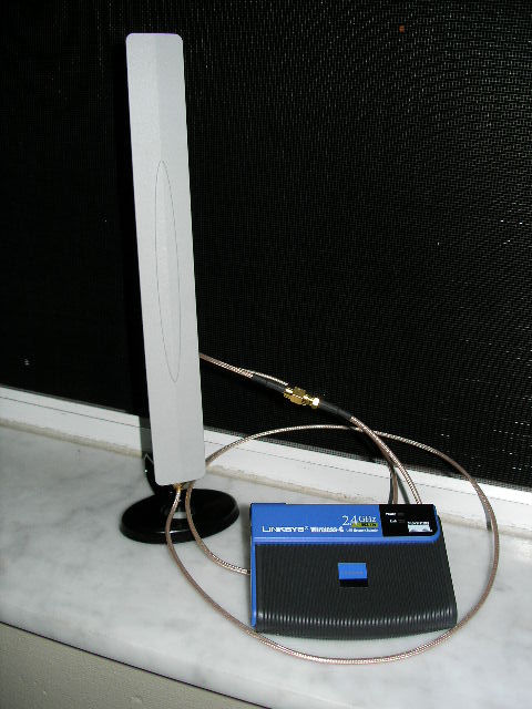
To connect the Wireless LAN (WiFi) equipments, coaxial cable and the antenna, we uses special connectors. There are several type of RF connector can be used at such high frequency. A good connector will normally have 0.3-0.5 dB losses. Unfortunately, a good connector will likely to cost around US$5-7 each. There is cheap connector that cost US$1 each. Unfortunately, bad connector will likely to give a significant signal loss and, thus, reducing the system operating margin.
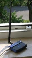
Wireless Antenna ConnectorsThis is the common wireless antenna connector, the connector is used to connect your acces-point or wireless card to external antenna.
Male N-Connector


Female N-Connector


N Connectors are usually found on external antenna and antenna cabling. It's usually cheaper to make your own cabling from RG-213 or LMR-400 cable and a couple of N-Connectors, than to buy fixed length cables from your Access Point manufacturer
Male RP-TNC


Female RP-TNC


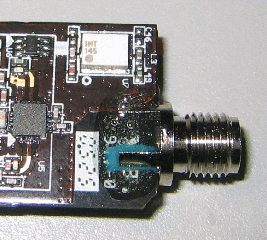
RP-SMA Connectors are usually found on access points such as the linksys WAP11
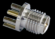
Male RP-SMA


Female RP-SMA


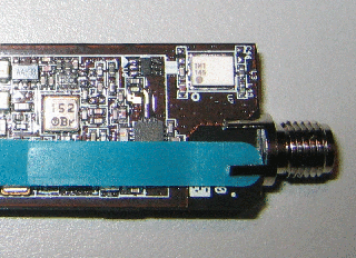
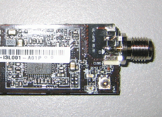
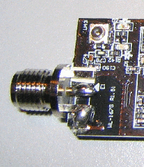
SMA connectors are usually found on PCI wireless cards, such as the Belkin F5D6001 or the Netgear MA311
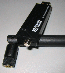
Male MC (Lucent) Connector


Female MC (Lucent) Connector


These connectors are usually found on pcmcia cards like the Buffalo WLI-PCM-L11G.
The 'RP' in RP-TNC and RP-SMA stands for Reverse Polarity. Hardware manufacturers seem to love using connectors that are hard to find. Most commercial converter cables and pigtails, convert the antenna connector to an N-Type connector, as almost all external antenna (yagi,omni or patch) come with N connectors. If you need to make an extension cable between the antenna and the pigtail/converter cable, we recommend using either LMR-400 or RG-213 cable as these are durable low loss cables suitable for 2.4 Ghz.
In a wireless system, antennas are used to convert electrical waves into electromagnetic waves. The amount of energy the antenna can ‘boost’ the sent and received signal by is referred to as the antennas Gain.
  1. Antenna gain is normally given in isotropic decibels [dBi]. It's the power gain in comparison to an isotropic antenna (antenna that spread energy in every directions with the same power....theoretical view it doesn't exist in reality!).
  2. Some antennas have their gain expressed in [dBd], it's the gain compared to a dipole antenna. IN this case you have to add 2.14 to obtain the corresponding gain in [dBi].
  3. The more an antenna has gain the more it is directive (energy sent in a preferred direction).
  4. Antenna coming with WLAN kits are generally whithout much gain (2.14 dBi ).
  5. Antenna gain is the same for transmit and receive ;-)

Parabolic antenna:
The parabolic reflector is independant of the frequency, it only affects antenna gain. So it means you can reuse your TV satellite dish for wifi :-)
The higher the gain the higher the directivity and so the more accurately it must be pointed.
The big challenge is to illuminate the parabolic reflector correctly. If illumination is too large or to concentrated there will be gain loss.

Antenna gain is measured in:

dBi - relative to an isotropic radiator
dBd - relative to a dipole radiator

The relationship between dBd and dBi can be represented in the following equation

0 dBd = 2.15 dBi

In most cases, we use dBi as our antenna gain measurement.
Leave your Cisco WiFi mobile phone at the door

Talk time
By Andrew Orlowski in San Francisco → More by this author

Published Thursday 17th April 2003 14:34 GMTGet The Register's new weekly newsletter for senior IT managers delivered to your inbox, click here.
Cisco has demonstrated a mobile phone that uses 802.11 wireless ethernet for use on "campus networks", which means enterprises with WiFi access.
It's more of a walkie-talkie replacement than what we recognize as a real mobile phone, but the importance of this convergence moshpit should not be underestimated.
document.

It isn't the first, by a long chalk. Symbol is just one of several vendors to market WiFi phones, announcing its own two years ago, but the market has failed to ignite.
Cisco claims that the 7920 - which looks like an early 90s GSM handset, only uglier - has two hour talktime and twenty four hours of standby time.

The savings are obvious: while in your office, you don't need to pay expensive landline or cellphone fees. Assuming your Internet connection is up to the job. Cisco says QoS is guaranteed with the 7920 - the mobile counterpart to its 7620 VoIP handset - but we'd like to like to hear what it sounds like with a saturated T1 serving an office of say 500 users, all talking simultaneously, with a BoFH downloading a set of Debian ISO images.
The drawbacks are equally obvious: you have to leave your phone at the door.
And the spectrum efficiencies and manufacturing economies of scale of the 2.5G and 3G digital technologies mean that the traditional mobile phone will never go away. Not for all the wishful thinking in the world.

Ericsson this week announced a dual-mode chipset for the Chinese market that combines CDMA2000 with 802.11, a much more promising combination. This combination of 3G plus WiFi has the best of both worlds: you don't pay exorbitant rates for data when you're in range of a friendly 802.11 base station, and you don't need to carry two (or three) phones.
The downside is cost: WiFi chipsets are eight to ten times more expensive than 2G voice chipsets.

But don't forget the fight taking place over the "last yard". This is an area both WiFi advocates and 3G evangelists both want to ignore. Thanks to Bluetooth, my phone can piggyback onto my DSL connection so I can use it to surf the web with Opera at high speed, bypassing the 4MB cap AT&T Wireless places on my phone's GPRS data usage. (It's a financial cap rather than physical limitation: once you go over the monthly fee, you pay a hefty amount for the extra bytes).
However, the vociferous (and well-funded) spectrum deregulation lobby in these United States is talking such nonsense, we must address this issue in more depth. Soon, m'dears, but not today. ®

wifi card

Scientific Atlanta/WebStar DPW939 Antenna MODIFiCATION


After along time searching I have found site about how to make external antenna for usb wifi card. I will explain the simillar as ASUS WL 167G antenna modification that I was found. Thank's to ronobvious.

This the step by step modification that I take from ronobvious website :

I recently bought a Ralink-based 802.11g adapter on eBay to use with the Aircrack-ng suite on a linux platform and decided to add an antenna connector to enhance its usefulness. This modification was partly inspired by the success I've had using a similarly altered Microsoft MS510 adapter and also by Tobias Hain's hack of an Asus WL-167g.

My USB device is a Scientific Atlanta/WebStar DPW939, which a rebadgedWL-167g so I won't cover the disassembly stage - this was nicelysummarized in the link above. The connector I used was a CONREVSMA03made by Linx Technologies and purchased through DigiKey. This connectoris a card-edge design, so it protrudes from the end of the USB stickalong the same axis. This is the connector:


Linx makes this connector for two different thicknesses of boards, .031" and .062". This adapter uses a board that measures around .035 so I went for the larger size. As it turns out, the .062 connector measures more like .070, so I believe the smaller size would have been a better fit. As a result, I needed to shim the gap to hold the connector's legs flat against the opposite side while I soldered the center pin. I used the thin end of a plastic tiewrap to snug things up.


The front side of the connector with the center pin soldered. Note the bare pad above the connector's upper leg, this is the ground pad from the original antenna which I removed.


Although it looks a bit blobby, I bridged the gap between the leg and the pad with a brass pin I salvaged from a jumper header of an old motherboard.


I gently clamped the case in a drill press vise, and drilled the end with a 1/4" bit. I should have clamped the case closer to the plastic end to prevent the drill bit from popping the two halves apart, but it still worked ok.


The back of the board has no bare copper to solder to, so I potted the legs with some epoxy. You can see that I snipped a piece of the tiewrap to fill the gap between board & leg.


The finished product. Although I'm showing it with a rubber duck antenna, I will mostly use a short pigtail to connect this to a much larger antenna =) In practice, I've found the Ralink USB adapters (I also use a similarly modded linksys WUSBGv4) to be markedly less sensitive than Prism or Zydas-based adapters when running in rfmon mode. Hooking them up to a big honking dish antenna certainly improves the situation.


That all I take from from ronobvious website.


You can also see the Linksys WSU54G v.4 Modification in http: modificationtech.blogspot.com
Or How to make "wifi cantenna " in:
http : makingwificantenna.blogspot.com